AI agents
Tell your agent what to build. It finds the parts, wires the circuit, writes and compiles the firmware, runs the simulation and reads the result back: scope values, serial output, even the display. You watch the circuit appear in your editor.
You“Build a weather station with an Arduino Uno, a BME280 and an OLED, and show me the display.”
library_search"bme280", "oled"…- bme280 · BME280 (temperature, pressure, humidity, I²C)
- ssd1306 · OLED 0.96" 128×64 (SSD1306, I²C)
library_getarduino_uno- pins, parameters and model of the Arduino Uno R3
circuit_edit7 parts, nets 5V, GND, SCL, SDA- project “Weather station” created, revision 1
circuit_check- 0 errors, 0 warnings
firmware_compileArduino sketch for the Uno- flash 22,390 of 32,256 bytes (69 %), RAM 594 of 2,048 bytes (29 %)
circuit_simulate2 s transient- 209,515 steps, firmware running
- serial: 21.00 C 1013.25 hPa 45.0 %
- display DS1: 128×64, 775 pixels lit
Agent“The weather station runs. The OLED shows 21.0 °C, 1013.2 hPa and 45 % humidity.”
Works with the agent you already have
An MCP server gives Claude Code and other MCP clients the same tools as the editor. There is no built-in chat; you use the agent you already have.
claude mcp add --transport http deckle-studio \
  https://deckle.io/mcp \
  --header "Authorization: Bearer YOUR_API_KEY"
What the agent can do
- library_search
- Finds parts and their pins
- circuit_edit
- Places and connects parts; the changes appear in the open editor
- circuit_check
- Finds wiring and supply mistakes
- firmware_compile
- Compiles firmware and loads it into the chip
- circuit_simulate
- Runs the circuit, measures with scope and logic analyzer, reads displays, steps through code
Firmware
Below, an Arduino Uno runs a compiled sketch in your browser. Change the temperature: the firmware reads the BME280 over I²C and redraws the OLED.
Arduino sketches, bare-metal C and Zephyr projects compile to the binary you would flash. Emulated chips: ATmega328P, RP2040, nRF52840, STM32F411, STM32G474 and ESP32-C3.
Arduino Uno, ATmega328P at 16 MHz
Open this circuitBME280 sensor values
I²C bus, decoded
Bus traffic appears once the firmware runs.
The sketch it runs
void loop() {float t = bme.readTemperature(), p = bme.readPressure() / 100.0, h = bme.readHumidity();oled.clearDisplay();oled.setTextSize(1); oled.setCursor(0, 0); oled.print(F("Weather station"));oled.setTextSize(2); oled.setCursor(0, 16); oled.print(t, 1); oled.print((char)247); oled.print('C');oled.setTextSize(1); oled.setCursor(0, 40); oled.print(p, 1); oled.print(F(" hPa"));oled.setCursor(0, 52); oled.print(h, 0); oled.print(F(" % rel. humidity"));oled.display();Serial.print(t, 2); Serial.print(F(" C ")); Serial.print(p, 2); Serial.print(F(" hPa ")); Serial.print(h, 1); Serial.println(F(" %"));delay(500);}Inside the editor
165 parts, among them real part numbers such as TPS7A20, BME280 and SSD1306. Add your own, or import a KiCad netlist.
PCB
Import a KiCad board with its netlist, or let the editor place and route one from your schematic. Either way you get the 3D view, the design rule check, copper analysis and the manufacturing files.
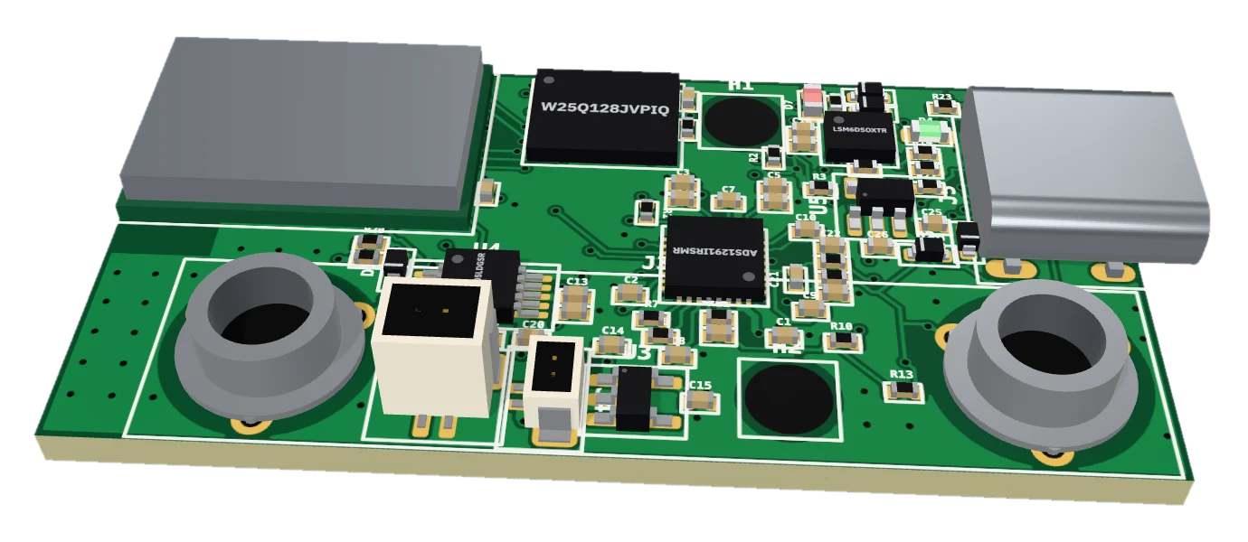
From schematic to routed board
This is the board of the game at the top of this page. Placement and routing are generated from the schematic, with rules per net type. Check the design rules, look at the board in 3D and export Gerber X2, drill files, BOM, placement file or a KiCad board. The files are not tied to one manufacturer.
| Supply | Track width from the current the simulation measured |
|---|---|
| USB pair | Routed as a pair, 90 Ω differential, lengths matched |
| RF | 50 Ω track, as short as possible, no vias |
| Crystal | Short, no vias, more clearance |
| Switch node | Wide and short, more clearance |
| High voltage | Clearance from IPC-2221B, from the voltage in the simulation |
Lessons
13 lessons, from Ohm's law to a first PCB. Each step is checked against the running simulation.
Try the first one here: move the fader.
Your first LED: Ohm's lawChange resistor R1 so that 10 to 20 mA flow through the LED.
–
Electronics basics
- Your first LED: Ohm's law
- Voltage divider: 3.3 V from 5 V
- The transistor as a switch
- Alternating flasher: capacitors set the timing
Programming the Arduino
- Blink: your first program
- Serial: the Arduino talks
- Analog values: the potentiometer
- Reading a button with INPUT_PULLUP
Sensors and displays
- Text on the LCD
- Sensor values change
Wi-Fi and the Internet of Things
- Getting the Pico W onto Wi-Fi
- Sending readings over MQTT
Your own PCB
- From schematic to PCB
Examples
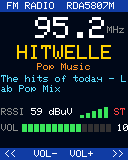
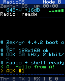
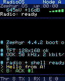
36 circuits come with the editor. These open directly; each screen shows what the circuit drew in the simulation.
- Jump & runSTM32F411, colour TFT and USB keyboard; the game is bare-metal C you can edit
- FM radioSTM32F411 with Zephyr, RDA5807M tuner, station search, RDS, sound
- Radio messengerTwo nRF52840 with TFTs exchange messages over a modelled 50 kHz link
- 16-bit CPU from 74xx chipsFour 74LS181 as ALU, ROM and RAM chips, draws on a TFT
- Web server on a Pico WWi-Fi driver and lwIP on a virtual network; the page switches the LED
- Full adder from 36 MOSFETsNine CMOS NAND gates, every transistor simulated

Simulation
Analog parts, logic and firmware run in one simulation. This scope shows a series RLC circuit, solved in your browser by the same engine as the editor: move a fader and the response changes.
Simulated live in your browser, with the same engine as the editor. Move a fader.
- Resonance
- 5.03 kHz
- Q factor
- 0.7
- Overshoot
- –
Accuracy
The circuit from the scope above, with the same netlist in this simulator and in ngspice 47. The largest difference over 4 ms is 902 µV, on a signal that swings up to 8.9 V.
The test suite repeats these comparisons and fails if a difference grows.
| Circuit | Largest difference |
|---|---|
| Series RLC, the circuit aboveTransient | 902 µV |
| RC low-passTransient | 7 µV |
| Diode rectifier with capacitorTransient | 8.1 mV |
| Red LED with resistorOperating point | 989 µV |
| NPN common emitterOperating point | 354 µV |
| NMOS switchOperating point | under 1 µV |
- deckle studio
- ngspice 47
- Signal peak
- 8.94 V
- Largest difference
- 0.90 mV
Difference between the two
Show the values as a table
| Time | deckle studio | ngspice | Difference |
|---|---|---|---|
| 0.00 ms | 0.000 V | 0.000 V | 0.00 mV |
| 0.25 ms | 5.088 V | 5.088 V | 0.37 mV |
| 0.50 ms | 6.533 V | 6.533 V | -0.21 mV |
| 0.75 ms | 4.923 V | 4.923 V | -0.11 mV |
| 1.00 ms | 4.524 V | 4.524 V | 0.01 mV |
| 1.25 ms | -0.107 V | -0.106 V | -0.36 mV |
| 1.50 ms | -1.385 V | -1.385 V | 0.12 mV |
| 1.75 ms | 0.078 V | 0.078 V | 0.11 mV |
| 2.00 ms | 0.431 V | 0.431 V | -0.01 mV |
| 2.25 ms | 5.184 V | 5.183 V | 0.38 mV |
| 2.50 ms | 6.392 V | 6.392 V | -0.06 mV |
| 2.75 ms | 4.898 V | 4.899 V | -0.12 mV |
| 3.00 ms | 4.565 V | 4.565 V | 0.01 mV |
| 3.25 ms | 0.135 V | 0.135 V | -0.39 mV |
| 3.50 ms | -1.411 V | -1.411 V | 0.04 mV |
| 3.75 ms | 0.004 V | 0.004 V | 0.12 mV |
| 4.00 ms | 0.435 V | 0.435 V | -0.01 mV |
All features
Show the full listSimulation, Instruments, Chips and boards, 165 parts in the library, Firmware, Virtual network, Schematic, PCB, Files, Accounts
Simulation
- Transient analysis and DC operating point
- Analog parts, logic and firmware in one run
- Trapezoidal, Gear 2 and backward Euler integration
- Slow motion, fast motion and faster quiet phases
- Temperatures from simulated power
- Sound from speakers, headphones and buzzers
- Antennas coupled by distance and orientation
Instruments
- Oscilloscope with trigger, cursors and up to 2 million points per channel
- Min, max, peak-peak, mean, RMS, frequency, duty cycle
- Voltage and current probes
- Logic analyzer with I²C, SPI and UART decoders
- Serial monitor with input
- Live view of TFT and OLED displays
Chips and boards
- Arduino Uno, Arduino Nano (ATmega328P)
- Raspberry Pi Pico, Pico W (RP2040)
- nRF52840, u-blox BMD-340
- STM32F411, STM32G474
- ESP32-C3 (RISC-V)
165 parts in the library
- Displays: SSD1306 OLED, ST7735 TFT, HD44780 LCD, TM1637, MAX7219, WS2812B
- Sensors: BME280, DHT22, DHT11, MPU-6050, LSM6DSOX, HC-SR04
- Motion and sound: SG90 servo, 28BYJ-48 stepper, LRA, speaker, buzzers
- Input: keypad, KY-040 encoder, buttons, potentiometer
- Analog: op-amp, NE555, LM393, LM386, TPS7A20, MCP73831
- Logic and memory: 74HC and 74LS chips, EEPROM, SRAM, SPI flash
- Radio: RDA5807M, antennas, AM and FM sources
Firmware
- Arduino sketches with common libraries
- Bare-metal C and Zephyr projects
- Breakpoints, step over, into and out
- Registers, local and global variables, call stack
- Flash and RAM usage after each build
- ROM editor with assembler for the 74xx CPUs
Virtual network
- Router with DHCP, DNS and NTP
- HTTP test server, and web pages from your own board
- MQTT broker; publish from the panel
- Traffic log of everything on the network
Schematic
- Several sheets and boards in one project
- Save a circuit as your own part
- Part editor with SPICE or Verilog models
- Circuit check for wiring and supply mistakes
- Tidy the layout with one click
- Undo, redo and keyboard shortcuts
PCB
- Automatic placement and routing
- 2 or 4 copper layers
- Net classes with impedance and clearance rules
- Track width from the simulated current
- Move, rotate and lock parts, then reroute
- Draw tracks and copper areas by hand
- Design rule check
- Color by voltage, layer or current, thermal image
- 3D view
Files
- Gerber X2, drill data, BOM and placement file as a ZIP
- KiCad board export and import
- KiCad netlist import
- Projects as JSON
Accounts
- Examples and shared circuits open without an account
- Free account for projects, your own parts and API keys
- MCP server for AI agents
- English and German, dark and light
Limits
- A simulation does not replace a prototype. Models cover what they were built for, and some effects are not in them.
- There is no field solver. Radio links and antennas are modelled, not solved electromagnetically.
- Review an automatically routed board before you order it, especially at high voltage.
Build your first circuit now
Runs in the browser. Try the examples without an account; sign up free to build your own circuits.